Thursday, February 19, 2015

Tub Cleanup, Prep and Coat

This is an overdue post from September 2014's work.  Time to get back on this.  I have been distracted by a 4 wheel drive van we just bought for camping trips.  The warm winter here in SLC has me motivated to get this thing on the road for spring.  Time to get back on focus.

Being a Texas FJ40, the tub actually isn't in terrible shape.  There is very little rot in the floor pans. The only areas of concern are under the roll cage mounts where it looks like it trapped water and rotted out.

Time:  2 weekends working about 4 hours each day (16 hours total labor, roughly)

Tools and Materials used:
1 - cup wire wheel
1 - radial wire wheel
Angle Grinder
80 grit sand paper
MEK
1 quart KBS RustSeal, black
4 red Scotchbrite pads
4 spray cans KBS Fusion Self-Etching Primer
150 grit sandpaper
Monstaliner Black Bedliner


These photos are representative of the whole tub condition.


I used a wire wheel on an angle grinder to strip the rust, spray paint, and poorly adhered OEM paint.


I roughed this all up with 80grit paper.  I wiped it all down MEK twice.  Then I painted it all with 2 coats of KBS RustSeal.


After a few days of curing time I scuffed up the RustSeal with red ScotchBrite pads.


Then I sprayed two coats of KBS Fusion Self-Etching Primer.


I let this cure for a few more days before I scuffed all of this up with 150 grit sand paper in prep for the bed liner.  I used black two part Monstaliner to coat the tub.  It was pretty simple to use.  I found the one gallon kit on ebay at a discount.  The gallon coated the entire tub interior with two coats, and I put a third coat in high wear areas like the driver and passenger foot areas.

I am missing completed photos right now so I will update sometime in the future....


Tuesday, August 12, 2014

Transmission Crossmember

I didn't take many pictures of this but the process was pretty straight forward. I set the transmission height where I wanted it.  This ties back to the engine angle.  And then I supported it with a screw type jack stand to fine tune the height.

Materials:
1.5" square X 0.120" wall steel tubing
Neoprene Spring Rubber; McMaster PN:  8630K118 70A Durometer
Qty-2, 7/16-18 X 1-3/4L Bolts
Qty-2 - 7/16 Flat Washers
Qty-2 - 7/16 Lock Washer
Anti seize to suit
Rust proofing paint

To fab the cross member I first started at the mounting points on the transmission and  drilled to clearance holes for 7/16 bolts on the transmission side and clearance holes for a socket on the road side.  I then cut a strip of the neoprene to act as my damper material that was 1 inch thick , 1.5 inches wide and 6 inches long. I drilled two clearance holes in the rubber for the hardware to pas through, but kept them tight.

I then worked toward the driver side.  I made a hard angle up to provide clearance underneath for the exhaust.  I then ran it flat to the top of the driver side frame, leaving about a quarter inch gap.

For the passenger side, I did the same.  I was only able to take the tube to the underside of the frame rail though.

After the basic structure was there, I cut a clearance for the nose cone saver on the Orion transfer case.  I then capped the cut out to make a a solid structure again, using 1.5"wide at 1/8" thick material.


To mount to the frame, I first bolted it to the transmission.  Then I clamped a piece of 4" X 4" X 1/8" angle to the inside of the drivers side frame, and the outside of the passenger side frame.  I tack welded it to the crossmember and drilled through holes into the angle and through both sides of the frame rail.  I then through bolted everything using 1/2-13 X 2-3/4" Grade 8 hardware and locking nuts.  After fit was confirmed I removed and painted using KBS rust seal..


Battery Box

I decided I wasn't going to install a heater in the FJ40.  So I decided to locate the battery box in the space left by the heater core.

Using the NAPA battery that came with it when I bought it, I cut a rectanle that fit snug around it as the base.


After that was welded, I added two tabs that I would bolt into the heater core mounting location.


I then mounted it into location and bent a piece of 1-1/2 X 1/8" flat stock to fit the inner fender profile.


 Mount it all in place and load test it with a few good stomps.


I also cut a piece of 18 gauge galvanized sheet that I had laying around to fill the hole.  The top tie down is a piece of 3" X 3" X 1/8" steel angle that I slotted and bolted to one of the upper heater core mounting holes.  Everything is painted with KBS rust stopper.


Thursday, July 24, 2014

Engine Positioning, Chassis Prep and Installation

Engine Positioning, Chassis Prep and Installation

While I was waiting for all the drivetrain parts to appear, I was also working on stripping out the old Toyota drivetrain and prepping for the Chevy V8 install.  Engine out was easy.  Disconnect half dozen wires or so, remove transfer case and transmission as one unit, pull radiator, battery, pull engine.  Done.  The only tool I bought was a Harbor Freight 2 ton engine hoist which I split with a buddy who is also doing an engine swap in his hot rod.

Before:


After:


It’s Lump:


I bought the Advance Adapters engine installation kit (AA 713124) for the swap.  Looking back, I wouldn’t do that again.  The kit was relatively expensive and only o.k.  I did find the directions helpful though.  The installation guide states the engine should be position 8-12 engines behind the shock tower.  The stubby little scab plate they provide is only 7 inches long (if I remember correctly) and would require you to locate the engine precisely before welding them in.  I did this.  What a waste of time.  The ends of the scab plate fell over two of the cutouts in the OEM frame rails so I would have lost about 5 inches of mediocre weld length.  And I need all the additional I can get.  I went and bought some 4” X 3/16” Flat Steel and cut two 17-1/2” pieces.  This length fell midpoint of two of the cutouts for welding convenience and would allow me to position the engine mount pretty much anywhere.

After cleaning out the engine bay, cutting out the old mounts and stripping the paint, I noticed two of the rivets holding the original frame together on the driver side near the engine mounts were loose and spinning in the frame.  My guess is that this is not good for structural integrity.  To remedy this I welding the “C” channels together top and bottom about an inch past the scab plate I planned to install. 


Crappy weld job:


After prepping and welding the channels together I then welded in the home made scab plates.  I added four ½” plugs as well, because ½” is the largest drill bit I have.


The next part was to locate the actual engine mounts.  The AA installation guide and internet wisdom say you want a 3-5 degree angle, tail down.  I don’t have an angle finder, and I think it is easier to work from level so I dug out my geometry skills.  I raised the tail 7 inches for about a 4.5 degree angle.  I then did some internet digging to find my lift springs in the front are about a 200 lb/in rate, so when the drivetrain is installed it would lower just over 2 inches.  Net result would be somewhere between 3 and 4 degrees.


I put the truck on jack stands and worked off of level from there: 


I then rolled the transmission under and lifted the engine over, bolted the two together and placed them.  I chose to push the engine as far forward as possible and maintain driveshaft length.  Well, the new drivetrain is much too long, so just plan on cutting your rear driveshaft.  Don’t forget to install the radiator when doing this so your fan doesn’t interfere.


I positioned the engine mount 9 inches back from the edge of the shock tower to the centerline of the mounting hole.  Leveled the mount, held my breath and tacked it in place.  I then positioned the opposite mount in the same location along the frame, leveled it front to back, and leveled it across to the other mount to ensure they were coplanar.   I placed the front edge of the mounts level with the top of the frame.  If I planned to do extreme rock crawling, I would have raised it as much as possible.


After tacking into place, I refit the engine and radiator, verified clearances, pulled everything back out and then finished welding.  One thing to note is that I plan to mount my engine on centerline of the chassis, instead of offset.  I did not notice any front driveshaft interference with the bell housing until extreme font axle travel.  If I run into issues later I will shift the engine or lower the bump stops.


In the end I am pretty happy with the result.  The crankshaft pulley to electric fan motor is a bit close, about ½”, and the Orion transfer case sits right about 2.5 inches below the frame.  I will brace the radiator, as per the factory, and build a skid plate for the transfer case.  Even hanging below the frame, with the lift is measure 18-1/2” inches from the ground.  I think there is some good clearance.


Final Install:


Wednesday, July 9, 2014

NV4500 to AA 3-spd T Case Adapter

I found a gently used 4wd version of an NV4500 on Craigslist and got a smoking deal on it.  It is the early GM version with the 6.3:1 first gear. I took it to be rebuilt at a local shop, J&G transmissions.  At the same time I ordered the Advance Adapters early GM NV4500 to Toyota 3 speed transfer case adapter.  Because the bellhousing that came with the GM had the internal slave cylinder mount, I decided to stick with the Toyota system and picked up the AA GM bellhousing and Toyota slave cylinder bracket mount as well.

Parts List:
Transmission:  GM NV4500 GM Code GBX
Bellhousing:  AA purchased from Summit Racing P/N ADD-712577
Trans to T-Case Adapter:  AA purchased from Summit Racing P/N ADD-50-0211
Slave Cylinder Bracket:  AA purchased from Summit Racing P/N ADD-716288

I am bad at remembering to take before photos so these dive right into the clusterfuck that is me prepping the transmission for the T-case.  To prep the trans, you have to remove the tailhousing that comes on it, remove the harmonic damper, cut the shaft down and then reassembly with the AA parts.  You need a special socket that is several hundred dollars to pull the damper and I couldn't find anyone to loan it or just do it for me without wanting serious coin or to do a full rebuild.  So I improvised....

Starting point:  This is the NV4500 as returned from being rebuilt, and after I bolted on the AA bellhousing.

This photo shows the stock GM tailhousing removed, revealing the harmonic damper that I need to get rid of.


This is the harmonic damper and locking nut on the output shaft of the transmission.  This needs to go.

With the help of  my angle grinder I made a cut into the harmonic damper.  I cut through the output side and slightly tapered it high, so as not to cut into the shaft on the inboard side.  You are cutting off a good section of shaft (consult the AA instruction sheet), so you don't have to worry about damaging the outboard side of the output shaft.

I rotated the damper about 45 degrees and made a second cut in the same manner.


I then took two pry bars and using counter pressure, broke out the notch that I made in the damper.  This piece is just cast iron so it should break fairly easily.  This gave access to the retaining nut.  I then used a punch and hammer to spin the nut off.  NOTE:  make your cutout where you can easily access one of the tabs on the nut to be able to hit it off with the punch.


Once the nut is off I used a Harbor Freight hydraulic puller to rip off the remaining section of the damper.  


Annoyingly, I couldn't get a machine shop to cut the shaft down while it was in the transmission.  It was a new rebuild so I didn't want to have to open it up, just to close it again.  The AA instructions say you can cut it off with a grinding wheel, but also show a cutoff dimension accurate to the hundredth of an inch.  With limited options i figured what the hell.  


This photo shows the concept.  I used my calipers to set the distance and scribe a line.  I clamped on some vise grips so I can keep the shaft spinning while I cut.  I first cut with a dremel tool because it was easier to hold steady.  Once I had a good channel I used a larger cut off wheel to cut through it.


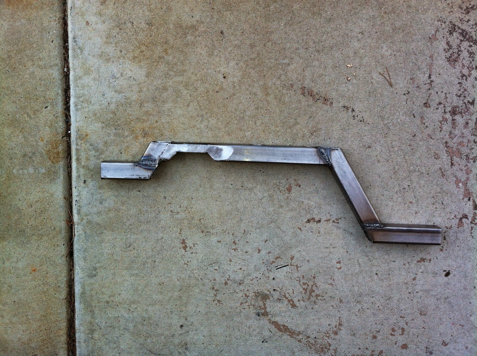
Here is the transmission output shaft cut off.  It came out pretty good.  I beburred the edges and checked square when finished, filing/stoning down the high spots on the shaft end.  Probably overkill for this application.  At this point it is ready for the adapter kit.

When you remove the damper, you remove the retainer for fifth gear so it is free to come apart.  The AA kit uses a split collar to clamp this into place.  They offer no torque guide so I looked one up on Roland's website and used 170 in-lbs to torque the cap screws down.  I also used a generous portion of blue loctite.


Then just slide on the AA stub shaft.


AA provides a bearing and snap ring that fits into/onto their adapter.  In this application they are really using the lock ring as a flange.  I tried to find clarification online and couldn't but the assembly matches their diagrams.  As I slid this assembly over the shaft the bearing popped out.  I would bolt on the housing and then slide in the bearing next time.  Not difficult either way.


Following what was done during the rebuild, I used some black RTV to make my gasket, rather than a gasket.  This is probably a bit heavy on the sealant.


Then just slide the housing on and bolt together.  The bolts are 12 point, 10mm sockets.  


Here is the transmission assembled and ready to be installed.  If you can't figure out how to bolt on the bellhousing you shouldn't be attempting this, so I left that out.